Service hotline
+86 0755-83975897

Release date:2024-05-21Author source:KinghelmViews:1845
RF connectors, as crucial bridges between RF circuits and devices, serve the primary function of transmitting high-frequency signals, encompassing microwave and radio frequencies. During the design and manufacturing processes, RF connectors must meet a series of stringent standards, including achieving low insertion loss, ensuring high impedance matching, reducing reflection loss, and maintaining high reliability to ensure signal transmission quality and stability.
RF connectors are similar to plugs and sockets that connect power lines to televisions. However, RF connectors transmit RF signals, and with higher frequencies, they hold a more significant role than regular connectors.
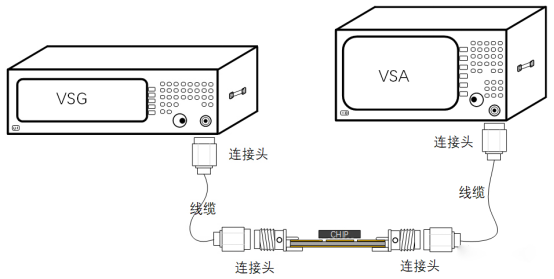
The following diagram illustrates an example of an RF connector connecting instruments and test boards, demonstrating that RF connectors and RF cables are essential components for signal transmission within a testing platform.
RF Connector Classification
RF connectors are typically designed for connection using threaded, bayonet, or plug-in methods, offering excellent mechanical and electrical performance. From a structural standpoint, RF connectors can generally be categorized into three main types:
Coaxial Connectors (cross-section diagram below)
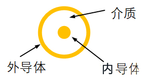
Inner Conductor: The inner conductor serves as the central conductor of the connector and is primarily responsible for transmitting RF signals. It is typically made of conductive materials such as copper or silver, offering good conductivity and transmission performance.
Outer Conductor: The outer conductor acts as the outer shielding layer of the connector, primarily used to shield against external interference signals and protect the inner conductor. It is typically made of metal materials such as copper or silver-plated copper, providing excellent shielding performance and corrosion resistance.
Three coaxial connector (cross-sectional diagram below)
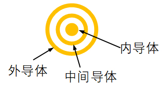
Compared to coaxial connectors, RF triaxial connectors feature an additional inner conductor, which improves isolation and shielding characteristics. The outer conductor serves as a fixation component.
Dual-core symmetrical connector (cross-sectional diagram below)
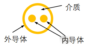
Similar to the commonly used twisted pair cables, the outer conductor in dual-core symmetrical connectors primarily serves a shielding function. In terms of transmission speed, this type of RF connector is not particularly high, and it is typically used for transmitting low-speed digital signals.
Note: The dielectric primarily provides insulation support.
According to the classification based on connection methods, RF connectors can also be divided into threaded connections, crimp connections, and bayonet connections, among others. The following diagram categorizes commonly used RF connectors based on their structure and connection methods.
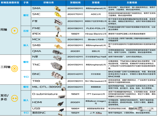
When you consider these as the complete classification of connectors, you are quite mistaken. These are just the tip of the iceberg for the RF connector family. In reality, there are many other types of RF connector interfaces, each applied to different scenarios and frequency ranges.
SMA Connector Classification
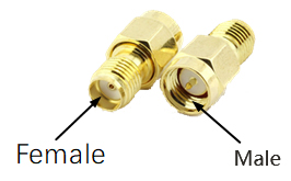
Let's take the commonly used SMA connector as an example. Firstly, it employs a threaded connection method, requiring one side of the outer conductor to have threads while the other has a nut. The inner conductor has a pin on one side and a hole on the other, allowing for a precise and snug fit. When the inner conductor has a pin, it is referred to as "male," and when it has a hole, it is referred to as "female."
SMA connectors can be classified into the following types based on their form and assembly methods:
1. SMA Straight Connectors: These connectors have a compact design and are typically used in high-frequency applications such as RF signal transmission and antenna connections. Common types of straight SMA connectors include SMA-J and SMA-K.
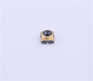
2. SMA Surface Mount Connectors: These connectors have a flat shape and can be directly mounted on circuit boards, commonly used in high-frequency circuit connections. Common types of surface mount SMA connectors include SMA-PCB and SMA-SMT.
3. SMA Threaded Connectors: These connectors have a robust design capable of withstanding significant mechanical stress, often used in military, aviation, and aerospace fields. Common types of threaded SMA connectors include SMA-J and SMA-K.
4. SMA Panel Mount Connectors: These connectors have a compact design and can be directly mounted on circuit boards, typically used in high-frequency circuit connections. Common types of panel mount SMA connectors include SMA-PCB and SMA-SMT.
5. SMA Adapter Connectors: These connectors have a unique design and can convert different types of RF connectors to SMA connectors, commonly used in testing and measurement fields. Common types of SMA adapter connectors include SMA-N and SMA-BNC..
Sizes of SMA connectors
SMA connector sizes are typically specified in millimeters, such as 2.92mm, 3.5mm, 4.13mm, etc. However, some suppliers may offer customized connectors with different sizes and naming conventions, so specific information should be obtained from the supplier's specifications.
Generally, the size of an SMA connector is related to the working frequency, with smaller connectors typically suited for higher frequency applications. For example, the SMA connectors with sizes of 2.92mm and 3.5mm have a higher frequency range than the 4.13mm connector, reaching up to 40GHz and 34GHz respectively, while the 4.13mm connector has a frequency range of 26.5GHz.
In summary, the selection and determination of the appropriate connector type should be based on specific application scenarios and needs, such as precision measurement, microwave communication, high-frequency communication, antennas, test instruments, and so on.
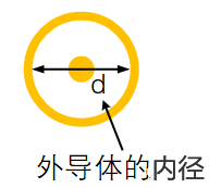
When we refer to the SMA diameter of 3.5mm/2.92mm/2.4mm, it refers to the inner diameter of the outer conductor.
Additionally, the tightness of the threads will also be indicated.
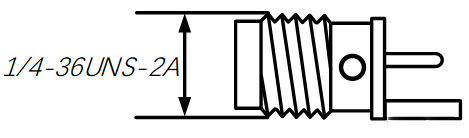
The earliest SMA diameter is 1/4-36UNS-2A, which is a Unified National Special thread size. This translates to a 1/4-inch thread with 36 threads per inch, "UNS" indicating a special series outside the UN series standard pitch. The thread accuracy is 2A for the external thread. Converted to metric, this is 6.35mm (multiplied by 25.4), with a pitch of 0.70556mm.
The 2.92mm SMA, commonly referred to as "K connector," is the most widely used in RF testing, where smaller diameter corresponds to higher operational frequencies.
The transmission impedance of a coaxial line is determined by the inner diameter of the outer conductor, the outer diameter of the inner conductor, and the dielectric constant of the material between the inner and outer conductors.
As the frequency of a coaxial transmission line increases, in order to maintain a constant impedance, it is necessary to reduce the spacing between the inner and outer diameters to decrease the wavelength of the electromagnetic wave within the transmission line, thereby ensuring signal transmission quality. Additionally, reducing the spacing between the inner and outer diameters can minimize the size of the transmission line, making it more compact and suitable for high-density wiring applications at high frequencies.
Different sizes of SMA interfaces
In our laboratory, the most commonly used standard SMA has an inner diameter of 4.13mm. Below is a list of several RF interfaces including SMA and similar SMA connectors that we frequently use.
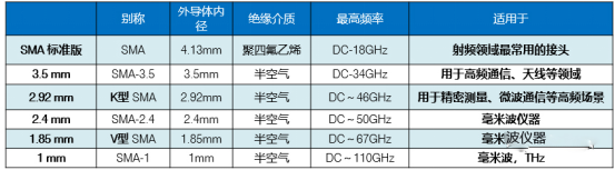
Experienced engineers know that similar-sized SMA connectors can sometimes be interchanged and connected mechanically. For example, SMA, 3.5mm, and 2.92mm connectors are mechanically compatible and can be connected to each other, while 2.4mm and 1.85mm can also be connected without causing serious mechanical damage.
However, forcefully connecting different-sized SMAs without considering their sizes can not only degrade shielding performance but also damage the connectors. From a performance standpoint, even slight interface differences (such as [sensitive word] size differences) can cause discontinuity at the contact surface, affecting electrical integrity.
The following figure shows the return loss when different-sized SMAs are directly connected. The minimum return loss occurs when 3.5mm is connected to 3.5mm. It can be seen that the return loss when different-sized interfaces are used is relatively poor.
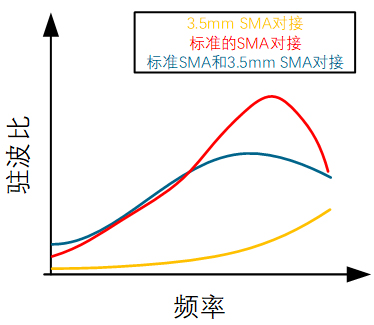
Generally, it is not advisable to mix different sizes of SMA connectors unless absolutely necessary.
The main indicators of RF connectors include the following aspects:
□ Frequency Range: Refers to the operating frequency range of the connector. Generally, connectors with a wider frequency range are more versatile. The design structure of high-frequency RF connectors is more complex and often employs special materials to ensure performance during high-frequency signal transmission. On the other hand, low-frequency RF connectors have relatively simpler design structures and can typically use conventional materials.
□ Insertion Loss: Refers to the signal loss caused by the connector during signal transmission. Connectors with lower insertion loss generally have higher signal transmission efficiency. Due to the unique nature of high-frequency signal transmission, high-frequency RF connectors typically exhibit lower insertion loss compared to low-frequency RF connectors. However, this also implies that high-frequency connectors are more expensive.
□ Isolation: Refers to the connector's ability to prevent signal interference during high-frequency signal transmission. The isolation performance of SMA connectors depends on the connector's design and manufacturing quality, primarily related to internal structure, contact area, and materials. Generally, the isolation of SMA connectors can reach 40dB or higher, and premium connectors can even achieve 60dB or more. Higher isolation results in less interference from adjacent signal lines, leading to increased stability and reliability of signal transmission. Therefore, when selecting SMA connectors, it's important to consider the isolation performance and choose a connector model and manufacturer that meets the requirements.
□ Impedance Matching: Refers to the degree of matching between the connector's internal impedance and the external circuit. Better impedance matching leads to less impact on signal transmission, resulting in higher stability and reliability of signal transmission. Standard RF connectors generally have an impedance of 50Ω or 75Ω.
□ Mating Cycles: Indicates the number of times the connector can be mated and unmated under normal operating conditions without affecting its performance and reliability. The mating cycles of SMA connectors are influenced by factors such as connector quality, manufacturing process, and operating environment. Typically, the mating cycles of SMA connectors are around 500-1000 times. However, in some high-end applications, the mating cycles may be higher, reaching several thousand or even tens of thousands. Therefore, when selecting SMA connectors, it's essential to choose a connector model and manufacturer based on specific application requirements.
□ Reliability: Refers to the connector's ability to maintain stable signal transmission and connection status under normal operating conditions. The reliability of SMA connectors depends on the connector's design and manufacturing quality, mainly related to internal structure, contact area, materials, and contact pressure. Generally, SMA connectors have high reliability and can work in harsh environments while maintaining stable signal transmission and connection status. High-end SMA connectors offer even higher reliability and longer service life, meeting the demands of some high-end applications.
The selection of RF connectors needs to comprehensively consider the above indicators, with different application scenarios requiring emphasis on different indicators. Generally, it is advisable to measure and verify actual usage before selecting RF connectors, ensuring that the connectors can meet practical requirements and maintain stability and reliability during long-term use.
Summary
In conclusion, RF connectors are critical components for high-frequency signal transmission and have a wide range of applications. When selecting RF connectors, it is important to closely consider the specific application scenarios and requirements, comprehensively evaluate their performance indicators and characteristics, and choose the most suitable connector model and size. It should be noted that RF connectors, such as the commonly used SMA type, are consumables with a basic mating cycle of approximately 500 times. Therefore, regular verification and timely replacement are necessary measures to reduce measurement errors caused by connectors or connection lines.
Copyright © Shenzhen Kinghelm Electronics Co., Ltd. all rights reservedYue ICP Bei No. 17113853