Croatian
 Bulgarian
 Chinese (Traditional)
 Arabic
 Sindhi
 Shona
Shona Scottish Gaelic
 Samoan
 Pashto
 Luxembourgish
 Kyrgyz
 Kurdish (Kurmanji)
 Hawaiian
 Corsican
 Amharic
 Uzbek
Uzbek Tajik
Tajik Sundanese
 Sesotho
 Sinhala
 Malayalam
 Malagasy
 Kazakh
 Chichewa
 Myanmar (Burmese)
 Zulu
Zulu Yoruba
 Telugu
 Tamil
Tamil Somali
 Punjabi
 Nepali
 Mongolian
 Marathi
 Maori
Maori Latin
Latin Lao
Lao Khmer
Khmer Kannada
 Javanese
 Igbo
Igbo Hmong
Hmong Hausa
Hausa Esperanto
 Cebuano
 Bosnian
 Bengali
 Urdu
Urdu Haitian Creole
 Georgian
 Basque
 Azerbaijani
 Armenian
 Yiddish
 Macedonian
 Icelandic
 Belarusian
 Welsh
Welsh Irish
Irish Swahili
 Malay
Malay Afrikaans
 Persian
 Turkish
 Thai
Thai Maltese
 Hungarian
 Galician
 Estonian
 Albanian
 Vietnamese
 Ukrainian
 Slovenian
 Slovak
 Serbian
 Lithuanian
 Latvian
 Indonesian
 Hebrew
 Filipino
 Catalan
 Swedish
 Spanish
 Russian
 Romanian
 Portuguese
 Polish
 Norwegian
 Korean
 Japanese
 Italian
 Hindi
Hindi Greek
Greek German
 French
 Finnish
 Czech
Czech Danish
 Dutch
DutchService hotline
+86 0755-83975897
 en
en 
Release date:2025-02-24Author source:KinghelmViews:1475
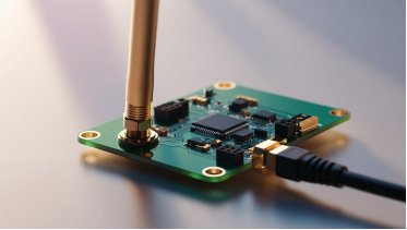
In the dazzling galaxy of wireless communication technology, PCB antennas stand out as a shining star. Each step from their design to application embodies the wisdom of technology and the spark of innovation. Today, let's delve into the core technologies of PCB antennas, unveiling their intriguing and captivating nature.
A PCB antenna is created by printing a conductive trace onto a printed circuit board (PCB). The trace can be designed in various shapes, such as straight lines, inverted F-shapes, serpentine, or circular patterns. The length of the trace, typically around a quarter of the wavelength, allows it to effectively radiate or receive signals.
● Gain: >2.0 dBi
● Operating Bandwidth: >150 MHz
● S11 (Return Loss) within Bandwidth: < -10 dB
● Input Impedance: 50 Ω
● VSWR (Voltage Standing Wave Ratio): <2.0
By designing specific metal conductor patterns on the PCB, electromagnetic waves are utilized for transmitting and receiving wireless signals. The performance of the antenna is influenced by factors such as conductor design and PCB material properties.
Typically, traditional FR4 or other rigid substrates are used. These materials are processed through techniques such as printing and etching. While FR4 provides good mechanical strength and stability, it is relatively thick and less flexible.
● Frequency: Determines the range of signals that can be sent and received. The physical size of the antenna is related to the frequency; lower frequencies require longer antenna lengths.
● Gain: Determines the level of radiated power. Higher gain results in a greater radiation range.
● Directivity: Defines the range of directions in which the antenna radiates and receives signals. Higher directivity means better signal transmission in specific directions.
● Impedance Matching: Necessary for matching with the radio frequency transmitter or receiver to ensure maximum signal transmission efficiency.
1. Appearance
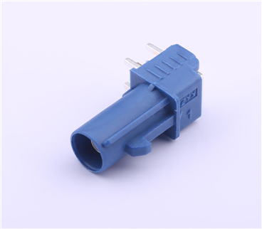
PCB antennas are printed on the circuit board and usually made from metal foil, while rod antennas are long and slender, typically made from metal rods.
2. Performance
PCB antennas generally have lower gain and narrower bandwidth but can be designed for multiple frequency bands and polarization directions. Rod antennas usually offer higher gain and wider bandwidth but are typically designed for single frequency bands and polarization directions.
3. Applications
PCB antennas are commonly used in small devices and low-power applications, such as smart home devices, wearable technology, and IoT devices. Rod antennas are generally used in larger devices and high-power applications, such as televisions, radio communications, and radar systems.
PCB antennas, as core components in the field of wireless communication, demonstrate the depth and breadth of technology from design to application. They not only optimize device performance but also expand the boundaries of wireless communication.
Copyright © Shenzhen Kinghelm Electronics Co., Ltd. all rights reservedYue ICP Bei No. 17113853