Service hotline
+86 0755-83975897

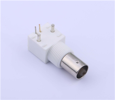
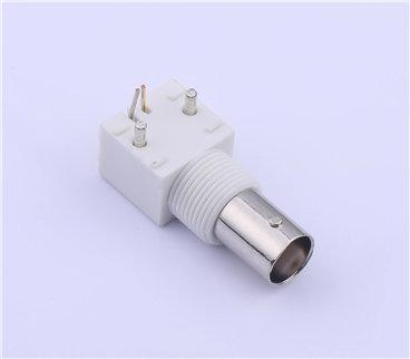
Release date:2025-02-19Author source:KinghelmViews:61
If we cannot extract data from the received signal, integrating data into the transmission signal becomes meaningless. That's why studying demodulation is essential.
The scope of demodulation circuits is extensive, ranging from simple improved peak detectors to complex systems combining coherent quadrature downconversion with sophisticated decoding algorithms executed by digital signal processors (DSPs).
Before demodulation, prepare a modulated signal and use LTspice to study the technique of demodulating an amplitude-modulated waveform.
In the amplitude modulation (AM) modulation page, we learn that generating an AM waveform requires four elements: a baseband waveform, a carrier waveform, a circuit, and a multiplier.
The following LTspice circuit will generate an amplitude-modulated waveform.
V1 is a 1 MHz sinusoidal voltage source that provides the original baseband signal.
V3 generates a 100 MHz sinusoidal wave as the carrier.
The operational amplifier circuit acts as a level shifter also halving the input amplitude. The signal from V1 is a sinusoidal wave swinging from -1 V to +1 V, while the output of the operational amplifier is a sinusoidal wave swinging from 0 V to +1 V.
B1 is an "Arbitrary Behavioral Voltage Source." Its "Value" field is a formula rather than a constant; in this case, the formula involves the shifted baseband signal multiplied by the carrier waveform. This allows B1 to perform amplitude modulation.
As discussed on the AM modulation page, the multiplication operation used for AM effectively shifts the base band spectrum to bands centered around the positive carrier frequency +fC and negative carrier frequency –fC. Therefore, we can consider AM as shifting the original spectrum up by fC and down by fC. Subsequently, multiplying the modulated signal with the carrier frequency will shift the spectrum back to its original position — that is, shifting the spectrum down by fC to center it again around 0 Hz.
1. Option 1: Multiplication and Filtering
The following LTspice schematic includes an arbitrary behavioral voltage source B2, which multiplies the amplitude-modulated signal with the carrier.
Result:
After modulation, the baseband spectrum is centered around +fC. Multiplying the modulated waveform with the carrier shifts the baseband spectrum down to 0 Hz, but simultaneously shifts it up to 2fC in this case, 200 MHz, because as previously mentioned, multiplication shifts the existing spectrum up by fC and down by fC.
Multiplication alone is insufficient for proper demodulation. What we need is multiplication combined with a low-pass filter; the filter will suppress the spectrum shifted up to 2fC. The schematic below includes an RC low-pass filter with a cutoff frequency of approximately 1.5 MHz.
Demodulated signal:
2. Option 2: Peak Detector
If we can extract the positive envelope of the amplitude modulation, we can reproduce the baseband signal without using a multiplier.
Starting from the peak detector, it consists simply of a diode followed by a capacitor. When the input signal exceeds the voltage across the capacitor by approximately 0.7V, the diode conducts; otherwise, it acts like an open circuit. Therefore, the capacitor retains the peak voltage: if the current input voltage is lower than the capacitor voltage, the capacitor voltage does not decrease because the reverse-biased diode prevents discharge.
To achieve a peak detector that only holds the peak value momentarily, we can introduce a parallel resistor across the capacitor to allow for discharge. The resistor should be chosen to discharge slowly enough to smooth out the carrier frequency but quickly enough to not smooth out the envelope frequency.
In LTspice, arbitrary behavioral voltage sources can be used to create amplitude modulated waveforms.
Amplitude modulated waveforms can be demodulated by passing through a multiplier followed by a low-pass filter.
A simpler and cost-effective approach is to use a peak detector with a parallel resistor, known as a leaky peak detector, which allows the capacitor to discharge at an appropriate rate.
Copyright © Shenzhen Kinghelm Electronics Co., Ltd. all rights reservedYue ICP Bei No. 17113853