+86-0755-83975897

news

News
Home -News -Industry Trends -Configuration and implementation of 5g application layer throughput test

Configuration and implementation of 5g application layer throughput test

Release date:2021-12-29Author source:KinghelmViews:1929

summary


 3GPP defines 5g NR new generation wireless communication technology from R15 protocol. By introducing new air interface and new architecture, 3GPP makes the bandwidth larger and spectrum efficiency higher, so as to greatly improve the wireless communication experience rate and meet the growing traffic demand of mobile Internet. According to the definition of ITU International Telecommunication Union,The peak data rate is the maximum data rate that can be achieved under ideal conditionsThe rate can be understood as the maximum bearing capacity of the systemThe embodiment of load carrying capacity.For 5g embB scenario, the maximum downlink peak rate is 20 Gbps; The uplink peak rate is up to 10 Gbps.  


In the actual 5g link scenario, there is often a certain gap between the application layer rate directly related to our experience and the physical layer rate. The configuration and parameter settings of the actual test environment will affect the application layer rate.  As more and more manufacturers begin to pay attention to the application layer throughput test, Anli has launched a complete set of 5g NR application throughput measurement scheme for module manufacturers. This paper introduces the construction and setting process of the test environment.  


Wiring diagram


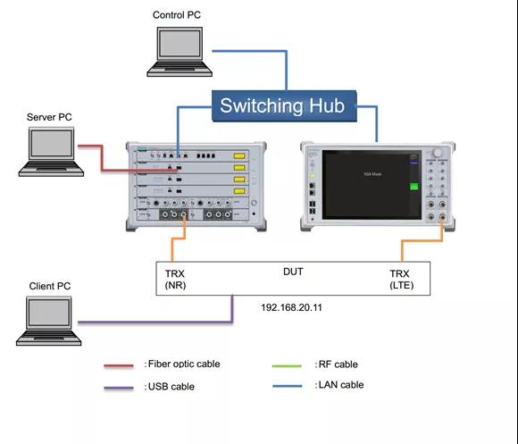
As shown in the figure below, on the basis of physical layer measurement, 5g NR analog base station (mt8000a) is extended to external server PC through optical fiber (supporting Linux system or windows system), 5g module is extended to client PC through USB network sharing, and finally iperf program is installed and run on server PC and client PC, so as to realize data filling and measurement of application layer.


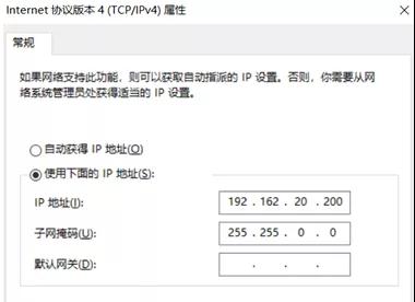
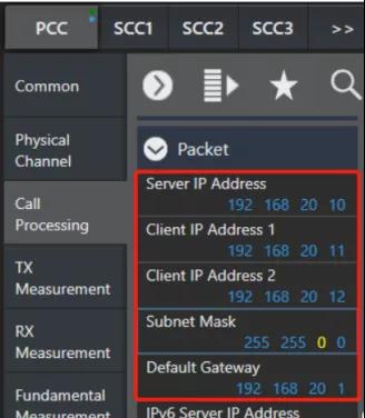
IP address of server PC: 192.168.20.200  DUT IP address: 192.168.20.11 (mt8821c default client IP address 1)
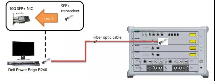
 IP address of client PC: connect through USB shared network and obtain the same IP address as DUT (192.168.20.11)  After installing the optical network card, the external server PC connects with the optical fiber interface on the mt8000a through optical fiber to expand the NR server to the server PC (detailed wiring is shown in the figure below).


Setting details


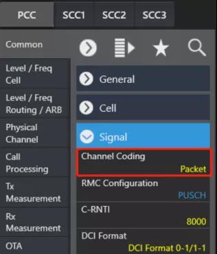
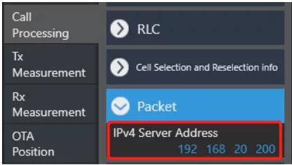
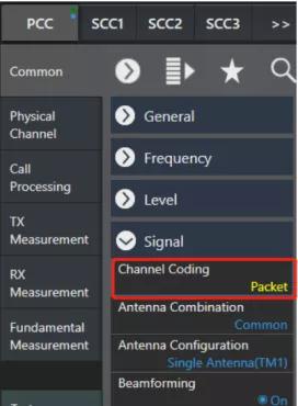
The control software interface settings of mt8000a are as follows (the figure above shows the ipdata measurement mode settings, and the figure below shows the NR server IP address settings).


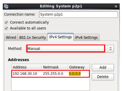
 The server PC settings are as follows (the above figure shows the windows system and the following figure shows the Linux system), and the subnet mask is set to 255.255.0.0 (the user can choose to set it according to the operating system type of the server).  


The settings of mt8821c are as follows (the figure above shows the ipdata measurement mode settings, and the figure below shows the LTE server IP address and DUT assigned address settings), and the subnet mask is set to 255.255.0.0.  


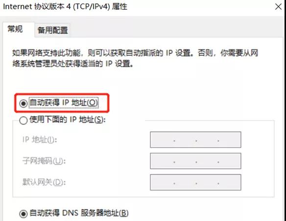
The IP address of the client PC is set as follows. In cooperation with APN, the specified IP address assigned by mt8821c can be automatically obtained.  


Physical layer debugging


Continued(Technical article | influencing factors and implementation of 5g NR peak rate), take the following frame structure as an example:

5ms single cycle: DDD ddsuu

D:GP:U(13:1:0)

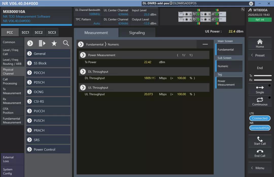
At sub-6ghz, μ= The bandwidth is 1100MHz, the modulation mode is 256qam, the airspace resource is 4x4mimo, the expansion coefficient is 0.8, the downlink overhead is 0.14, and the peak theoretical rate of 5g NR can be calculated to be 1.86 Gbps. As shown in the figure below, the measured 5g NR downlink physical layer throughput data of a module is one thousand eight hundred and nine point one one seven Mbps。


Add APN


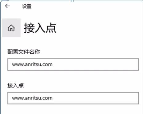
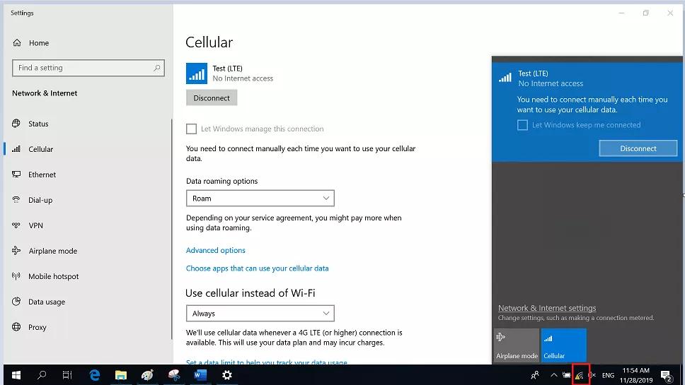
After the physical layer is switched on, the DUT network is shared to the client PC through USB, APN is added and connected, and the specific settings are as follows (after that, packet filling and measurement can be carried out):"Network and Internet settings" -- > "cellular" -- > "advanced options" -- > "add access point" -- > enter www.anritsu.com in the profile name and access point input boxes COM and save the settings.


Iperf filling and measurement


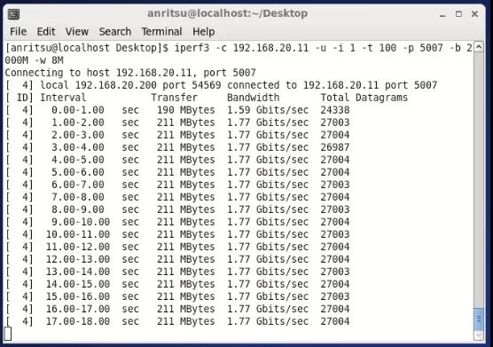
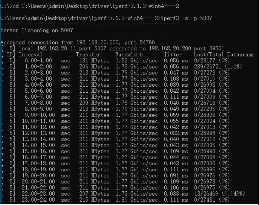
The client PC executes the following instructions to listen for packets:  iperf3 -s -p 5007    The server PC executes the following instructions for UDP packet filling:  iperf3 -c 192.168.20.11 -u -i 1 -t 50 -p 5007 -b 2000M -w 8M    

The serverPCThe filling results are as follows (taking Linux system as an example):


 clientPC listening results are as follows:  


Conclusion:    The throughput of the physical layer is 1809.117 Mbps, and the measured rate of the UDP application layer is 1.77g bps.  


Measured maximum throughput of application layer


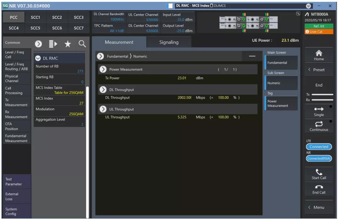
Continued(Technical article | influencing factors and implementation of 5g NR peak rate),Recently, a chip supports 95% duty cycle function, and the expected throughput value is 2.02 Gbps. Through joint debugging with the chip, its frame structure can be set as ddsu, where s (D: GP: U) is 11:1:2 (this frame structure is not specifically reflected in the expansion coefficient defined in 3GPP ts38.306). Under this frame structure, the maximum downlink throughput of the physical layer tested on the Anli mt8000a is 2.002 Gbps, as shown in the following figure:


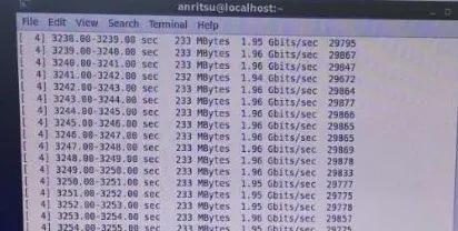
At this time, the measured rate of UDP application layer is 1.95 Gbps.


This article is reproduced from“Anritsu”, support the protection of intellectual property rights. Please indicate the original source and author for reprint. If there is infringement, please contact us to delete  


Links: Sitemap金航标萨科微KinghelmSlkorRUFRDEITESPTJAKOSIMYMRSQUKSLSKSRLVIDIWTLCAROPLNOHIELFINLDACSETGLHUMTAFSVSWGACYBEISMKYIHYAZ

Service hotline

+86 0755-83975897

Wifi antenna

GPS Antenna

WeChat

WeChat