Service hotline
+86 0755-83975897
 en
en Release date:2022-04-10Author source:KinghelmViews:2682
Abstract:
In actual life, terminal that we use is generally equipped with single antenna or MIMO antenna, which have high gains and relatively wide 3dB beam in single antenna radiation direction diagram. In many long-distance communication demands, strong directional antenna (e.g. base station antenna) is needed to make up for space attenuation.
Directional Antenna
In Xuege Antenna column, omnidirectional oscillator antenna (antenna from electromagnetic wave generation to symmetric oscillator) is introduced first. Advantage of this kind of antenna is to realize comprehensive coverage, but the gains are not high and communication range is limited. Besides, during the actual use, omnidirectional antenna needs larger clearance area.
Suppose under dark invisible environment, a flashlight has power of 3 W and is very bright in spite of very small bright domain, a beam in dark. Power of a common bulb is 60 W and the 360° bright domain is very broad, but the brightness is relatively weak. Though power of bulb is 20 times of that of flashlight, to illuminate certain indefinite item in the line of sight, flashlight is inevitably applicable to bulb, in spite of the invisible bright domain. The both have their respective advantages and disadvantages. Flashlight is similar to directional antenna and bulb is similar to omnidirectional antenna.
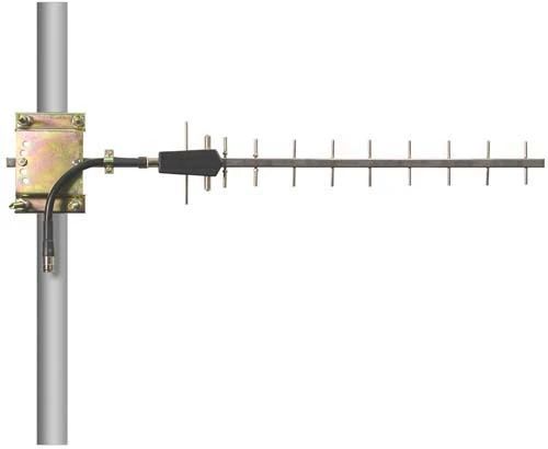
Comparatively speaking, directional antenna, which has more centralized radiation energy and higher gains than omnidirectional antenna, is more suitable for long-distance point-to-point communication. The directional end-fire antenna in directional diagram - yagi antenna will be constituted after increasing a passive reflector and parallelly arranging eight passive directors, which could be widely found in HF, VHF and UHF wave brands.
As shown by figure below, directional diagram of H face of excited half wave oscillator is a circle, which signifies the radiation energy can realize 360° coverage in horizontal plane and is non-directional. But after placing one or several additional passive oscillators side by side, the directional diagram in H face will be directional.
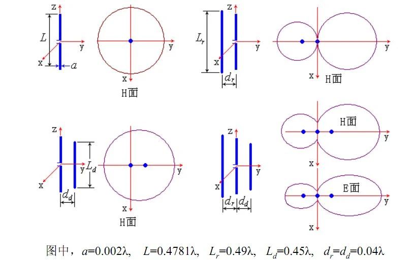
In general, the larger the number of directors is, the stronger the directionality will be; but it isn’t linear relationship, for induced current on various directors of end is gradually weakened.
Besides yagi antenna, conventional directional antenna also includes parabolic antenna, Vivaldi antenna and microstrip patch antenna with floor (HFSS and CST simulation comparison of patch antenna and characteristic module analysis and application of patch antenna).
Why array antenna is used?
The antenna system arranged and constituted by many identical single antennas (e.g. symmetrical antenna) as per the definite law is also called antenna array. Independent units commonly known antenna array shall be called array elements or antenna units. It will be a linear array or planar array.
Directionality and aperture efficiency are mentioned in the article Discussion of Planar Caliber Antenna. To meet the increasingly strict demands of the systems such as communication, radar, navigation, microwave landing, disturbance and anti-dfforisturbance, it is necessary to array antenna units to improve antenna grains, for when “everybody adds fuel, the flames rise high”.
Next, let’s lean why gains could be improved after antenna arraying (taking uniform linear array for instance):
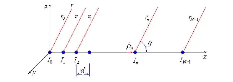
As shown by figure above, every antenna is regarded as point source after neglecting size and shape of antenna and coupling factor among units. Considering that far zone can be approximatively seen that rays from various antenna units to designated point are parallel, wave-path difference between the nth unit and the 1st unit is:
Excitation current of the first antenna unit in the figure is excitation phase difference of adjacent two units, and far zone radiation field of the nth unit (arbitrary form) can be written below:

Total field can be recorded below:

Suppose array factor is:

It can be simplified into:

Put forward and normalize common factor, and normalized factor will be obtained:

When total radiant power is the same, the ratio of power density on the maximum direction of main lobe and average power density of the whole space is defined as directivity factor. Neglecting antenna loss, directivity factor can be regarded as actual gains of antenna. Similarly, the formula will be as follows if just uniform linear array is considered.

With respect to side shot array, the following equation will be established when number of units N is relatively large:

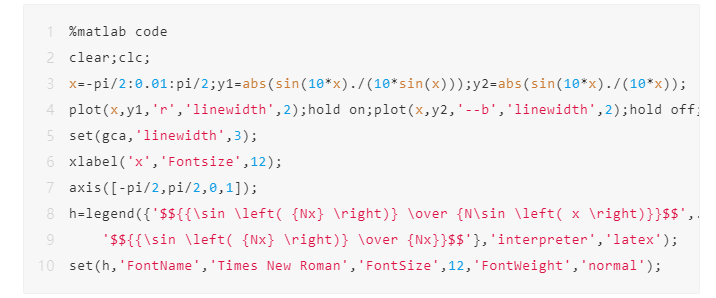
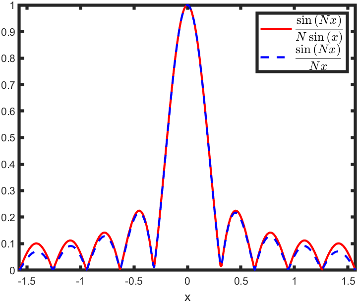
In case of bringing into integral operation, the further operation may be realized by substituting upper and lower limits of integral.

Therefore, for uniform linear array with uniform amplitude and the same phase, the largest gains can be expressed below:
It is arraying length herein. This shows when unit spacing is fixed, number of units and gains shows a linear relationship theoretically. Meanwhile, the formula signifies when arraying size is fixed, it isn’t necessarily useful for improving array gains when increasing antenna units blindly. Thus sparse array is derived. Sparse array can reduce antenna units to a certain degree to lower engineering cost, and besides, it is freer in arranging array elements. Dad, which, furthermore, could get more excellent antennae performance.
Suppose figure below is linear array of a patch antenna, the fixed total arraying length is: number of units * unit spacing = 100 mm. Since Translate operating in CST modeling supports all-variable modelling, dimension of y-axis direction of antenna unit can be fixed as 12.5 mm and direction on x-axis is set as 100 mm/unit. Set number of units as a variable for reference, and corresponding actual gain changes of different numbers of units will be simulated in case of uniform arraying under fixed total arraying length.
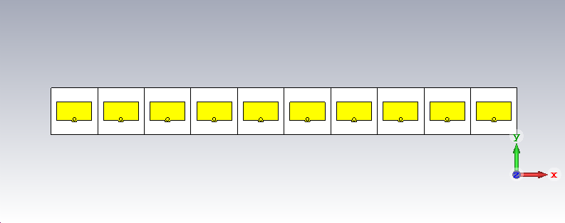
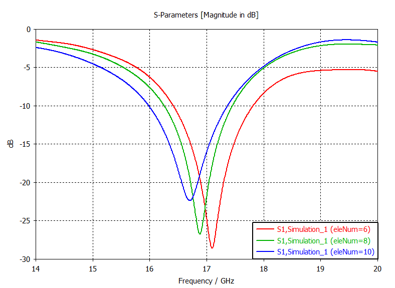
Figure below shows circumstances of different numbers of units: Port reflection coefficient of Unit 1. 17GHz S11 is basically at -15dB or so, and port matching is excellent.
Under the dimensions of 12.5 mm×100 mm, corresponding maximum gains of 17GHz will be as follows when aperture efficiency is 100%.

Below shows directionality of 17GHz under the same-phase excitation of all units by comparing with different numbers of units.
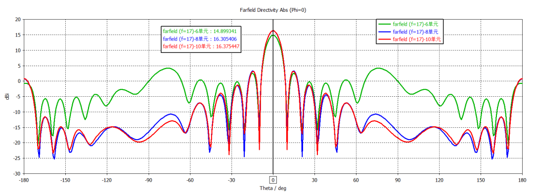
According to above result, if number of units is too sparse, directionality will be lowered and the first pair of petals will be relatively high. Numbers of units (8 and 10) have basically consistent directionality. The former has large unit spacing and isolation among units is more advantageous.
In general, on the basis of determining arraying size, blindly increasing antenna unit could not always improve antenna gain; on the contrary, it may result into isolation deterioration among antenna units, which, furthermore, lowers antenna gain. Unit spacing and number of units should be determined according to beam scanning angle range, unit isolation and the specific requirements (e.g. actual cost budget).
Above are the contents to be shared to everyone. Hope to help you ~~
The article is from network for reprint only. Opinion, stance and technology of this article are irrelevant to this website. If any infringement, please feel free contact us to delete it!
Copyright © Shenzhen Kinghelm Electronics Co., Ltd. all rights reservedYue ICP Bei No. 17113853
