Service hotline
+86 0755-83975897

Release date:2024-09-19Author source:KinghelmViews:1712
To help customers make the most of SLKOR's products, the company has recently introduced the SL-W-TRS-5.5Dx digital infrared thermopile chip and its associated application solutions, offering comprehensive technical support. The technical team at Shenzhen SLKOR Micro Semicon Co., Ltd. comes from Tsinghua University and Yonsei University in South Korea, leading the company with new materials, processes, and products. They have mastered internationally advanced third-generation silicon carbide power device technology early on. SLKOR is a high-tech enterprise integrating electronic product design, development, production, and sales, providing reliable products and technical services to its customers. With rapid development, the company is introducing more new products to serve customers and make a positive contribution to the semiconductor industry, striving to become a "semiconductor leader."

Sun Gaofei (left), Zhang Junjun(middle) and Professor Li Jianxiong from Tsinghua University
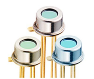
SLKOR's Marketing Director, Sun Gaofei, introduced that the "SLKOR" brand's digital infrared thermopile is designed for non-contact temperature measurement applications in fields such as medical devices, smart wearables, smart home appliances, industrial temperature monitoring, non-contact body temperature measurement, forehead thermometers, student ID cards, and electronic sentinels.
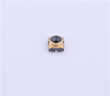
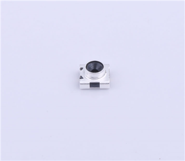
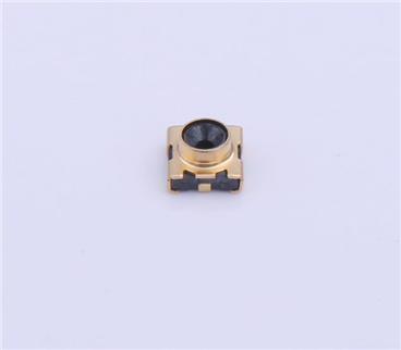
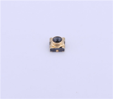
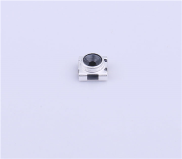
The SL-W-TRS-5.5Dx chip features a direct-mount digital infrared thermopile designed for non-contact temperature measurement. It includes an integrated thermopile sensor and dedicated processing chip, allowing communication and data reading via an I2C bus without additional external components. The chip comes with standard metal tube options of 5mm and 8mm and can operate in temperature environments ranging from -40°C to 130°C. It measures temperatures of liquids, objects (surface temperatures), and body temperatures, with a measurement range of -40°C to 530°C.
The SL-W-TRS-5.5Dx series models are:
SL-W-TRS-5.5D1 — Bare sensor, TO-46 package, field of view (FOV) = 90°
SL-W-TRS-5.5D2 — TO-46 package with a 5mm high metal tube, FOV = 75°
SL-W-TRS-5.5D3 — TO-46 package with an 8mm high metal tube, FOV = 60°
SL-W-TRS-5.5D4 — TO-46 package with a 5mm custom metal tube, FOV = 75°
SL-W-TRS-5.5D5 — TO-46 package with a 5mm custom metal tube, FOV = 75°
SL-W-TRS-5.5D6 — TO-46 package with a 3.5mm custom metal tube, FOV = 75°
2. Typical application circuit diagram
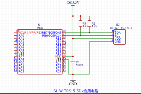
2.1 The circuit principle of SL-W-TRS-5.5Dx
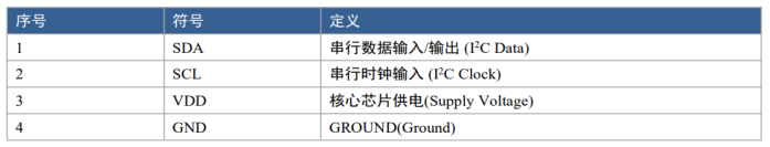
The SL-W-TRS-5.5Dx device has four pins, including power and I2C bus connections, with an allowable supply voltage range of 2.3 to 3.6V. The sensor itself has low power consumption, and a 0.1uF capacitor is sufficient between the power and ground. If the sensor is located far from the power supply, a 10uF capacitor can be added to ensure stable power and reduce noise.
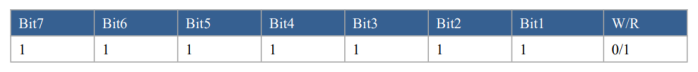
2.2 The SL-W-TRS-5.5Dx device supports the I2C communication protocol for serial communication. The choice of communication protocol is based on the state of the CSB pin. The I2C bus uses SCL and SDA as signal lines, both connected to VDDIO through pull-up resistors to maintain a high level when the bus is idle. The I2C device address of the digital device can be configured via the Chip_Address in register 0x92, with a generic 7-bit address of 0x7F for I2C communication (as shown in the figure below).
I 2C Device generic address
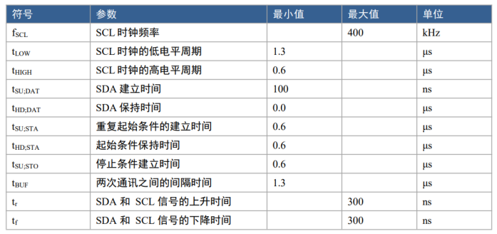
I 2C The bus line characteristics of the SDA and SCL lines in the I2C bus
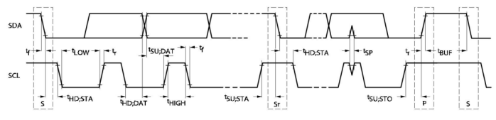
I 2C Timing diagram
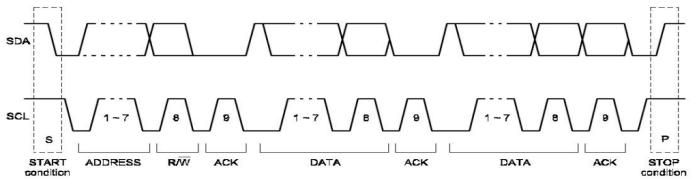
I 2C Communication protocol
2.3 When SCL is high and SDA transitions from high to low, it signals the start of I2C data communication. The I2C master device sequentially sends the 7-bit address of the slave device, followed by the R/W control bit to choose read/write operations. Upon recognizing the address, the slave generates an acknowledgment signal by pulling SDA low during the ninth SCL (ACK) cycle. When SCL is high and SDA transitions from low to high, it marks the end of I2C data communication. Data on SDA must remain stable while SCL is high, and it can only change when SCL is low.
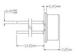
3.TO-46 Metal tube package and dimensions
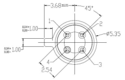

3.1 Pin definitions
3.2 Structural design requirements
For models with a metal optical cup, if structurally permissible, the sensor lens may extend beyond the top surface of the device housing. If there are aesthetic restrictions requiring the component to be recessed, the design must ensure that the structure avoids obstructing the device's field of view.
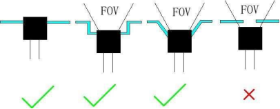
For products that require the use of the TO46 bare sensor chip due to specific needs, the sensor's inherent field of view (FOV) is approximately 90 degrees. Because infrared thermopile sensors are very sensitive to light and heat, a stable ambient temperature minimizes stray light interference, resulting in more accurate measurement results. Generally, direct measurement with the sensor is not recommended; structural integration is needed for product applications. The sensor itself comes with a silicon optical filter, which attenuates infrared signals and can lead to lower measurement results. Unless absolutely necessary, additional filters should not be added.
4.1 Thermal design requirements
The ambient temperature significantly impacts measurement accuracy, so it is important to keep the sensor in a stable environment to avoid interference from heat sources. Therefore, it should be located away from high-heat-generating components. On the PCB, it is advisable to design slots around the sensor, placing it in an isolated area.
4.2 Measurement distance
The sensor's output characteristics are more influenced by distance when measuring at close range (generally within 20mm of the sensor lens). Therefore, for measuring human body temperature, a recommended distance of approximately 2-5 cm is advised. For measuring other objects, the distance can be extended as long as the field of view requirements are met.
5. Program design
5.1 Standard Mode: In this mode, the I2C configuration is implemented via register settings, allowing direct I2C data reading.
5.2 Sleep Mode:
In Sleep Mode, the SDA line is repurposed as an INT output, and I2C is disabled while SCL remains high. Only the sensor channel is compared, not the internal temperature sensor output. In I2C IDLE mode, set sleep_en = 1 and mode_en = 1 to enter sleep, lasting from 100 ms to 25.6 s (8-bit). Upon waking, a conversion is performed to obtain the ADC calibration output. The channel combination checks are performed using the calibrated ADC raw data against a threshold to trigger an interrupt if conditions are met. Registers can be configured to trigger the interrupt when values exceed or fall below the set threshold. After the comparison, the device returns to sleep. By default, the SDA remains high; when an interrupt occurs, it is pulled low and returned to high after 50 ms. This interrupt signal can wake the MCU. Once the MCU detects the INT signal, it pulls SCL low for more than 10 ms, returning to I2C IDLE mode with sleep_en = 0.
6. Design Considerations
In application design, it is essential to understand the characteristics of the measurement object (liquid, solid, or human body), measurement distance, and temperature range. Based on the application environment, algorithm optimization is crucial to enhance measurement accuracy.
The original chip algorithms are designed to ensure specified accuracy only under thermal equilibrium and isothermal conditions (where there is no temperature difference across the sensor package). Any temperature gradient within the sensor package can adversely affect measurement accuracy. Situations that can cause temperature differences include heat-generating components located on or near the bottom or sides of the sensor, or when the sensor is positioned very close to the object being measured, which can lead to localized heating of the sensor.
If you have questions or requirements related to the products and application solutions from SLKOR, please feel free to contact us. We are here to provide dedicated support and assistance!
Copyright © Shenzhen Kinghelm Electronics Co., Ltd. all rights reservedYue ICP Bei No. 17113853