Service hotline
+86 0755-83975897

Release date:2025-02-20Author source:KinghelmViews:458
The following is a case study of automotive ethernet debugging performed at Inspectron, a company that designs and manufactures borescopes, embedded Linux systems, and camera inspection tools.
The automotive ethernet signal path is bi-directional , so hardware transceivers must be able to discern incoming data by subtracting their own outbound data contributions from the composite signal. If one were to directly probe an automotive ethernet data line, a jumbled superposition resembling a bus collision would be acquired. To make sense of the individual signals being sent, bi-directional couplers can be used.
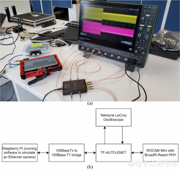
Figure 1 (a) The hardware configuration used to debug an automotive ethernet setup involves two DUTs, passive fixtures to adapt from automotive ethernet to SMA, and a calibrated active breakout fixture with bi-directional couplers to isolate traffic from each direction. The oscilloscope will analyze both upstream and downstream traffic. (b) The block diagram of the test setup. Source: Teledyne LeCroy
Intermittent signal loss occurred between the ROCAM mini-HD display and the Raspberry Pi. One method to capture an intermittent loss of data transmission is a hardware Dropout trigger.
Anomalous amplitude modulation or baseline wander issues can often be caught by triggering at a high threshold, slightly above the logic +1 voltage level (for the non-inverting input from the split differential signal).
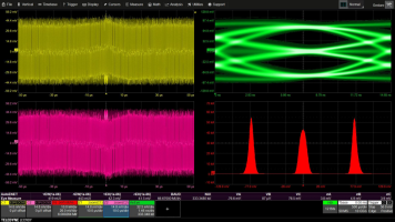
Figure 3 The three red histograms in the lower right grid show an asymmetry in the eye pattern due to intermittent anomalous amplitude modulation. The edge trigger raised to a high voltage threshold, catches an instance of the anomalous amplitude modulation. Source: Teledyne LeCroy
Copyright © Shenzhen Kinghelm Electronics Co., Ltd. all rights reservedYue ICP Bei No. 17113853