Service hotline
+86 0755-83975897
Release date:2021-12-28Author source:KinghelmViews:4454
Learn antenna is a dry cargo antenna technology column focusing on antenna simulation and debugging, supplemented by theoretical principles, including introduction to antenna, principle introduction of various antennas, simulation software modeling, design, debugging process and ideas. If you want to see the content or technical problems, you can write a message at the end of the text.
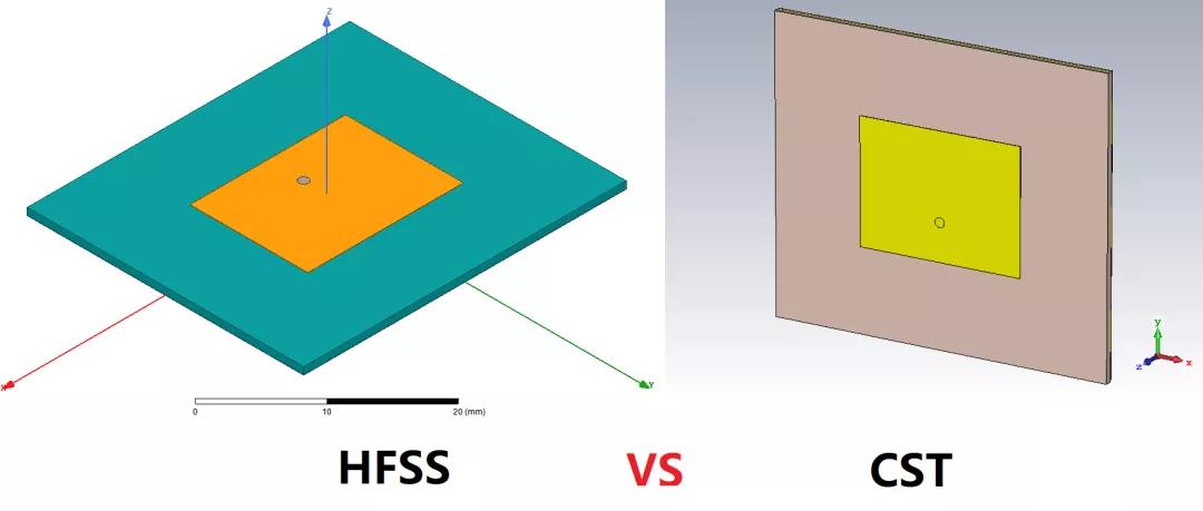
01、Brief introduction
At present, the built-in solution algorithms in HFSS include: finite element algorithm (FEM), integral equation algorithm (ie), high frequency algorithm (SBR + Solver), hybrid algorithm (febi, ie region), domain decomposition algorithm (DDM, fa-ddm), time domain algorithm (transient), eigenmode algorithm (CMA), eigenmode solver, etc https://zhuanlan.zhihu.com/p/113897875
In fact, most people simulate simple antennas and filters. Using the finite element algorithm of HFSS and the adaptive mesh generation and encryption technology of the software itself, setting the convergent Max MAG delta S (default 0.02) is enough to meet their simulation requirements.

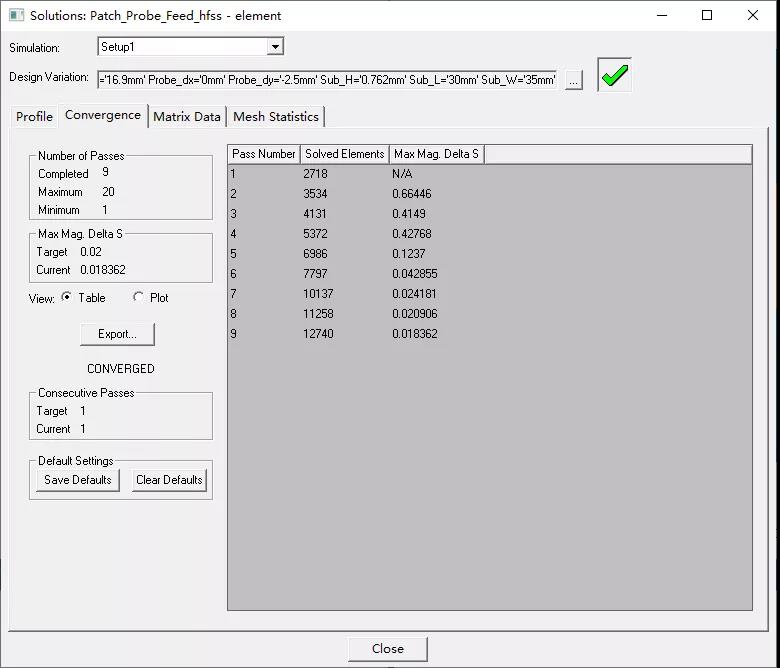
The use of software and the setting of other algorithm solvers will not be described here.
CST just makes up for the short board of HFSS simulation UWB, but its simulation accuracy in small size, circular and other structures is not high. As shown in the figure below, the triangular mesh generation of HFSS is particularly delicate at the edge, especially the circular structure accessories, while the hexahedral mesh generation of CST is too regular.
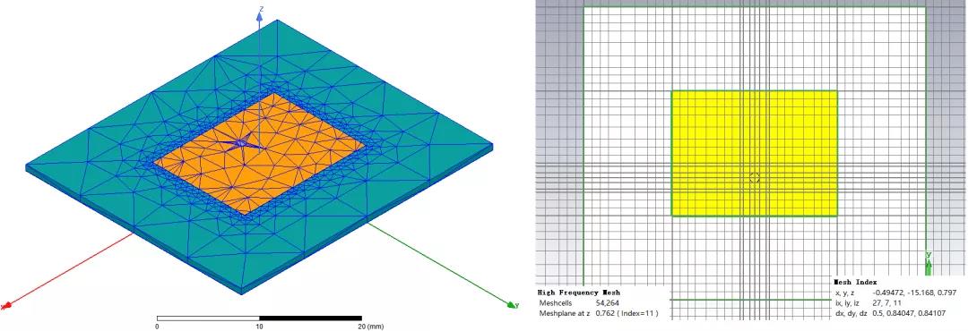
Although the local mesh of CST can be used to encrypt the local mesh near structures such as gaps and circles, beginners may still be the fool adaptive subdivision of HFSS, which is more humanized.
CST software uses the full wave time-domain simulation algorithm of electromagnetic field - finite integral method (FIT) to discretize and iteratively solve the Maxwell integral equation. Due to the time-domain algorithm fit, it only needs to be solved step by step without matrix inversion. This inherent characteristic determines that its suitable simulation structure covers small, medium and large, and can achieve good performance. The calculation amount of volume moment method, finite element method and finite integration method (reflected in CPU time and required memory) is respectively proportional to the 3rd, 2nd and 1.1 ~ 1.2nd power of the number of grids n. It can be seen that the computational force requirements of finite integration method are lower than those of HFSS finite element method.
For CST software, time domain solver is also commonly used. In addition, it also has frequency domain solver, eigenmode solver, integral equation method, asymptotic calculation and multi-layer medium algorithm.
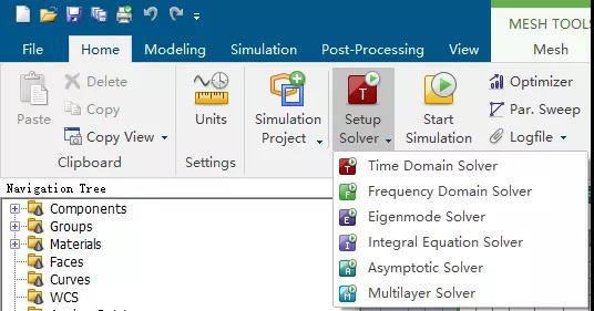
In the next section, we will compare the simulation accuracy of the two software, mainly focusing on the FEM + automatic mesh generation encryption simulation of HFSS and the time domain solver and frequency domain solver of CST.
The common feeding methods of rectangular patch antenna include side feeding and back feeding. This tweet uses back feeding for simulation analysis.
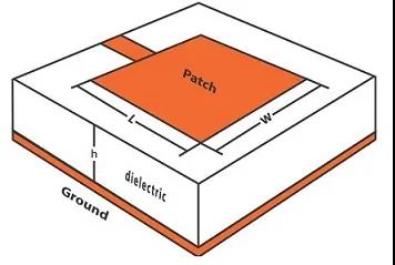
Firstly, Rogers 4350b with substrate thickness of 0.762mm is selected, and the resonant frequency is 5.8GHz. (slide left and right to see the complete formula)
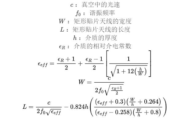
According to the above formula, the width and length of the patch antenna are 16.9mm and 13.3mm respectively.
clear;clc;path = mfilename('fullpath');i=strfind(path,'');path=path(1:i(end));cd(path);addpath(genpath(strcat(path,'hfssapi-by-Jianhui Huang')));try % 填写路径 % tmpPrjFile:生成的aedt或者hfss(安装hfss15以下的后缀名为.hfss)项目文件的路径名 % tmpScriptFile:生成的vbs脚本文件的路径名 tmpPrjFile = 'F:vbsScriptPatch_Probe_Feed.aedt'; tmpScriptFile = 'F:vbsScriptauto_code.vbs'; % hfssExePath:HFSS软件的路径 hfssExePath = 'D:softwareHFSS15AnsysEM18.2Win64ansysedt.exe'; % 创建一个可读写vbs脚本文件. fid = fopen(tmpScriptFile, 'wt'); %创建一个新的HFSS项目并[敏感词]一个新的设计文件. hfssNewProject(fid); Design_name='element'; hfssInsertDesign(fid, Design_name); Patch_W=16.9;Patch_L=13.3; Sub_W=35;Sub_L=30;Sub_H=0.762;copper_H=0.035; Probe_dy=-4;Probe_dx=0; Inner_R=0.5;Diel_R=exp(50/60*sqrt(1))*Inner_R;Outer_R=1.5;L0=2; % hfssVariableInsert(fid,DesignName,variableName, value, units,flag) hfssVariableInsert(fid,Design_name,'Patch_W', Patch_W, 'mm',1); hfssVariableInsert(fid,Design_name,'Patch_L', Patch_L, 'mm',1); hfssVariableInsert(fid,Design_name,'Sub_W', Sub_W, 'mm',1); hfssVariableInsert(fid,Design_name,'Sub_L', Sub_L, 'mm',1); hfssVariableInsert(fid,Design_name,'Sub_H', Sub_H, 'mm',1); hfssVariableInsert(fid,Design_name,'copper_H', copper_H, 'mm',1); hfssVariableInsert(fid,Design_name,'Probe_dx', Probe_dx, 'mm',1); hfssVariableInsert(fid,Design_name,'Probe_dy', Probe_dy, 'mm',1); hfssVariableInsert(fid,Design_name,'L0', L0, 'mm',1); hfssVariableInsert(fid,Design_name,'Inner_R', Inner_R, 'mm',1); hfssVariableInsert(fid,Design_name,'Diel_R', 'exp(50/60*sqrt(1))*Inner_R', 'mm',2); hfssVariableInsert(fid,Design_name,'Outer_R', Outer_R, 'mm',1); % 画基板 % hfssBox(fid, BoxName, Start, Size, Units, Color, Material, Transparency, flag) hfssBox(fid, 'Sub1', {'-Sub_W/2', '-Sub_L/2', '0mm'}, {'Sub_W', 'Sub_L', 'Sub_H'}, 'mm',... "(0 128 128)", "Rogers RO4350 (tm)", 0, 2); % 画贴片 hfssBox(fid, 'Patch', {'-Patch_W/2', '-Patch_L/2', 'Sub_H'}, {'Patch_W', 'Patch_L', 'copper_H'}, 'mm',... "(255 128 0)", "copper", 0, 2); % 画GND hfssBox(fid, 'GND', {'-Sub_W/2', '-Sub_L/2', '0mm'}, {'Sub_W', 'Sub_L', '-copper_H'}, 'mm',... "(128 128 128)", "copper", 0, 2); % 画同轴部分 % 画同轴内芯 % hfssCylinder(fid, CylinderName, Axis, Center, Radius, Height, Units, Color, Material, Transparency, flag) hfssCylinder(fid, 'Inner', 'Z', {'Probe_dx', 'Probe_dy', 'Sub_H+copper_H'}, 'Inner_R','-(Sub_H+copper_H*2+L0)', 'mm',... "(128 128 128)", "copper", 0, 2); hfssCylinder(fid, 'Diel', 'Z', {'Probe_dx', 'Probe_dy', '-copper_H'}, 'Diel_R','-L0', 'mm',... "(0 128 128)", "vacuum", 0, 2); hfssCylinder(fid, 'Outer', 'Z', {'Probe_dx', 'Probe_dy', '-copper_H'}, 'Outer_R','-L0', 'mm',... "(128 128 128)", "copper", 0, 2); % 地板开过孔 hfssCylinder(fid, 'GND_hole', 'Z', {'Probe_dx', 'Probe_dy', '0mm'}, 'Diel_R','-copper_H', 'mm',... "(255 128 0)", "vacuum", 0, 2); % 布尔操作 hfssSubtract(fid, {'Outer'}, {'Diel'}, true); hfssSubtract(fid, {'Sub1','Patch','Diel'}, {'Inner'}, true); hfssSubtract(fid, {'GND'}, {'GND_hole'}, false); % 保存项目文件到指定路径 hfssSaveProject(fid, tmpPrjFile,1); % Close the HFSS Script File. fclose(fid); disp('vbs脚本已生成!');catch disp('程序出现异常!'); fclose(fid);end
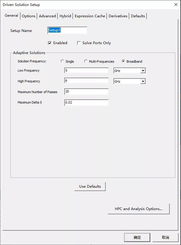
After the modeling is completed, add the region by yourself, set the radiation boundary conditions and the setup of analysis, and then the simulation can be carried out (after the subsequent boundary and analysis are synchronized, they can be established in the script).
Analysis设置

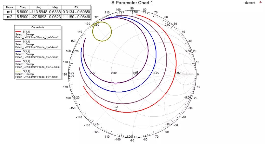
At this time, the simulation results can be seen that the antenna resonant frequency is biased to low frequency, and the input impedance deviates from 50 ohms.
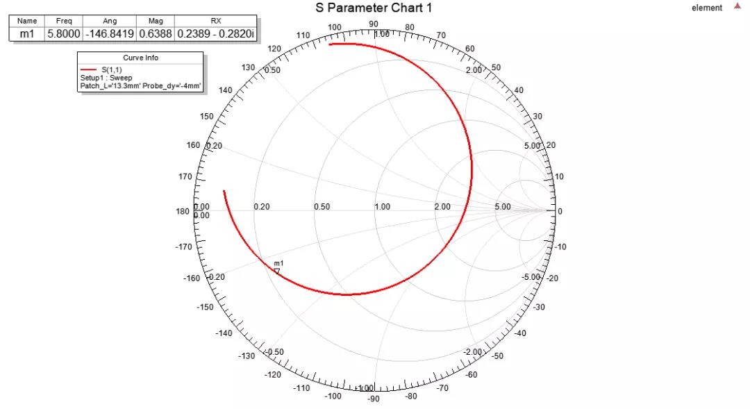
At this time, someone will say that adjusting the antenna is metaphysics. How can I know which variables to adjust and how many variables to adjust? Can I directly use optimization? In fact, those who have understood the relevant principles of patch antenna know that at this time, they only need to adjust the length of antenna and the position of feed deviation from the center. The former affects the resonant frequency and the latter affects the matching of antenna.
It can be seen from the above figure that the impedance matching is better when the feed point is 2.5mm away from the center of the patch antenna.
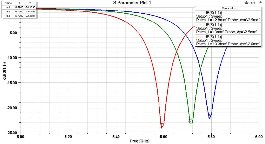
However, at this time, the resonant frequency of the antenna is still biased to the low frequency of 5.6ghz, so the setting of 5.8GHz back fed patch antenna can be completed by appropriately shortening the antenna length.
矩形贴片天线长度扫参结果
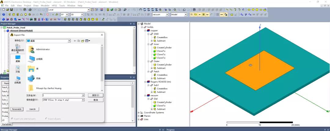
Select modeler - > export in the menu bar above HFSS and save it in step format.
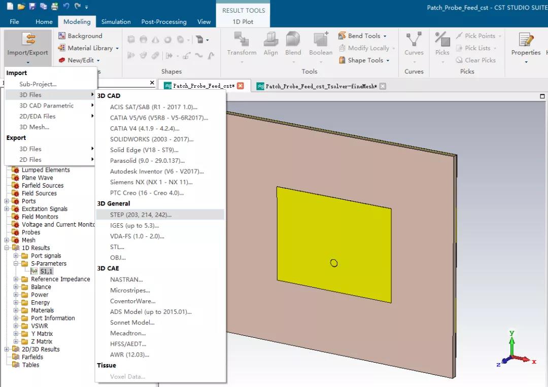
Then open CST, select and import the above step file under export, delete irrelevant models such as region, and set material properties and boundary conditions.
Using the time domain solver and the default mesh generation setting, the simulated resonant frequency is 5.759ghz, which is 40MHz different from the HFSS simulation results.
CST time domain meshproperties and S11 results
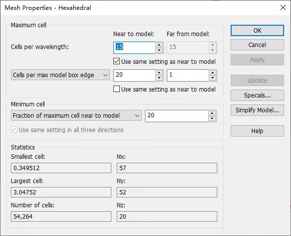
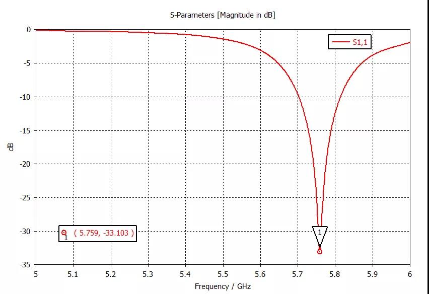
The solver of the above model is directly changed to the frequency domain solver, and the grid division is set according to the figure below. The simulated resonant frequency is 5.825ghz, which is about 25MHz different from the HFSS simulation result, which is very close.
CST frequency domain meshproperties and S11 results
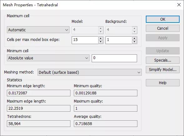
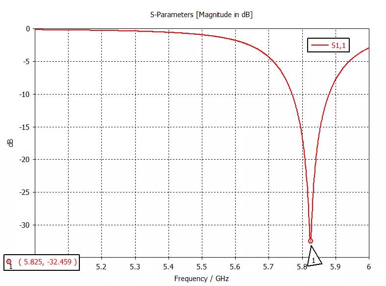
It takes a lot of time and energy to write basic code and make comments. I hope you will like to share more!
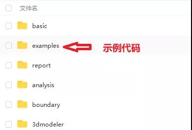
Code sharing area
hfssapi-by-Jianhui Huang
Download link (follow-up code is continuously updated in the following link):
https://pan.baidu.com/s/1N0EE3Uv7krkypfzi9vxCvg
Extraction code:o5p5
The code has been encapsulated and packaged as a p file, which cannot be modified. Each time you download and overwrite it, you can swap it according to the function comments!

The "kinghelm" trademark was originally registered by golden beacon company. Golden beacon is a direct selling manufacturer of GPS antenna and Beidou antenna. It has a very high popularity and reputation in Beidou GPS navigation and positioning industry. The R & D and production products are widely used in BDS satellite navigation and positioning, wireless communication and other fields. The main products include: rj45-rj45 network, network interface connector, RF connector adapter, coaxial cable connector, type-C connector, HDMI interface, type-C interface, pin and bus, SMA, FPC, FFC antenna connector, antenna signal transmission waterproof connector, HDMI interface, USB connector, terminal line, terminal board terminal, terminal strip, RF RFID tag Positioning navigation antenna, communication antenna connecting wire, rubber rod antenna, sucker antenna, 433 antenna, 4G antenna, GPS module antenna, etc. It is widely used in aerospace, communication, military industry, instrumentation, security, medical and other industries.
This content comes from the network / microwave RF network. This website only provides reprint. The views, positions and technologies of this article have nothing to do with this website. If there is infringement, please contact us to delete it!
Copyright © Shenzhen Kinghelm Electronics Co., Ltd. all rights reservedYue ICP Bei No. 17113853