Service hotline
+86 0755-83975897
Release date:2021-12-28Author source:KinghelmViews:2448
5g - the fifth generation wireless communication technology, as a global hot topic, is an indisputable fact. As many experts have said, this technology will bring lower delay and faster data communication rate, and will lead to the explosive growth of interconnected devices.
The larger bandwidth demand of 5g network requires that the antenna array must be completely redesigned. From unit to array, to feed network, to full model verification and application scenario evaluation, perfect fine simulation and optimization design are required.Microwave simulation Forum
Using ANSYS HFSS, the design and comprehensive verification of 5g antenna array can be easily completed in only 8 steps. In addition, HFSS can help engineers optimize various antenna performance indicators, such as:
Gain - the strongest signal radiation direction.
Beam control -It can control the signal radiation in a certain direction。
Return loss - return energy reflected from the antenna
Sidelobe level - unwanted signal radiation direction.
After the design process, the obtained array antenna has higher focusing gain, lowest return loss and sidelobe level, and the direction can be controlled.
Step 1:Find the antenna unit template through the ANSYS HFSS antenna Kit (ATK)
The first step of 5g antenna array design is to find the appropriate antenna unit template through HFSS antenna toolbox (ATK). The antenna unit will define an identical part that is ultimately used to replicate into a series of antennas (antenna array).

First select an antenna type from the library of the antenna toolbox (ATK), and then enter the operating frequency and antenna substrate properties.
After a few seconds, the antenna toolbox (ATK) will generate the initial geometry of the antenna unit. HFSS can also calculate the gain and return loss of antenna elements.
With the antenna unit, engineers can substitute it into a periodic array. Substituting cells into a series of replication designs helps to improve the gain.
In the first step, the antenna unit is self evaluated. This process can now be repeated using periodic elements of an infinite antenna array.
It is easy to understand that the distance of other antennas in the array will affect the characteristics of gain, return loss, sidelobe return and beam control. Of course, these characteristics can also be optimized by adjusting the antenna orientation.
After selecting the best array orientation, the infinite array can be changed into an idealized finite array by defining the array factor.
In this example, a 16x16 square antenna array is simulated.

Step 3:Design of finite antenna arrays using domain decomposition method
The design of antenna array does not need an idealized model. Therefore, the next step is to build a real simulation in order to better understand the interaction between each antenna element and the edge of the array.
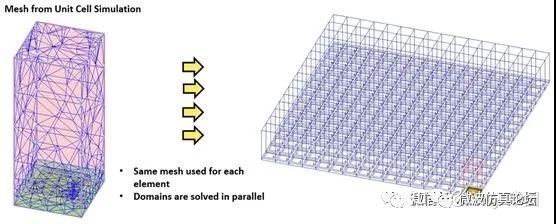
The simulation method is completed by domain decomposition (DDM). The domain decomposition method copies the mesh of a single cell and applies it to the geometry defined in the second step. The boundary of each mesh overlaps and stitches with adjacent meshes to evaluate the coupling of adjacent array elements.
Once the grid is created, ANSYS HFSS can be used to evaluate and optimize antenna gain, return loss, sidelobe level and beam control. The accuracy is better than the method in step 2.
If the transmission direction of the signal cannot be controlled, 5g antenna will be meaningless. Here, the "finite array beam angle calculator" of HFSS can be used to calculate the phase shift required to point the beam in a specific direction according to the signal frequency and scanning / phase angle. These angles will be used to locate the array antenna in the spherical coordinate system.
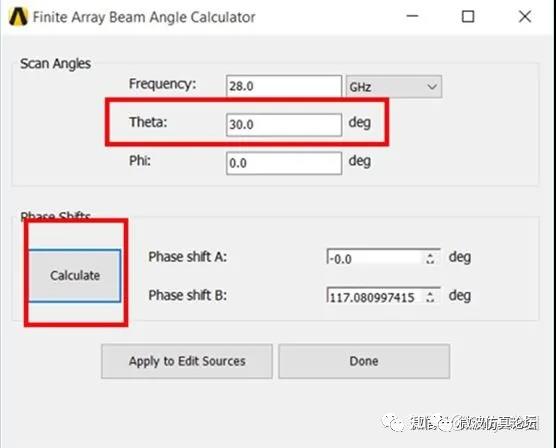
The calculator can be based on the grid created in step 3,Determine the relationship between the antenna in the array and the specific scanning angle of the beam.
Step 5: Design antenna array feed network
The next step is to design the feed network of the array.
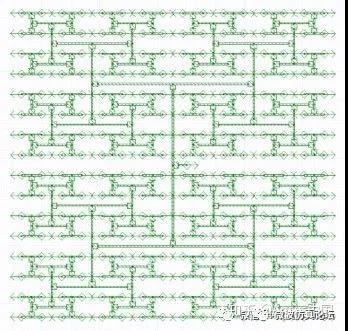
Firstly, it is necessary to determine the target phase relationship and amplitude, and then design and iterate the feed network in HFSS until it meets the standard.
When iteratively designing the feed circuit of the array, we can predict how each iteration will affect the amplitude and phase relationship.
After completing the cabling and optimizing the settings of each array, you can start connecting all its designs in a complete simulation project.
Step 6:Connect all antenna array models in one simulation design
The finite element model created in step 3 can now be routed according to the beam angle calculation in step 4 and the feed network in step 5.
In addition, a phase shifter can be added to control the signal. The phase shifter can be selected from the component library according to the phase angle calculated in step 4.
Next, linear network analysis (LNA) can be carried out to evaluate the return loss index for this nearly completed simulation project.
Step 7:Push the antenna array excitation combination to ANSYS HFSS
Now you need to push the excitation results from LNA to HFSS. In other words, the mismatch loss from the feed network is transmitted to HFSS in the form of amplitude and phase values, and then the results are drawn as a system gain diagram.

The gain can more accurately reflect the radiation performance of the antenna in all directions.
Step 8:Test and evaluate the actual performance of the antenna in the actual use environment
The last step is to evaluate its design performance in the antenna service environment [yx1].
This process involves electrically large scenes and platforms, and the ray tracing (SBR) technology of HFSS can be used for system level research. This study can calculate the ability of the antenna to transmit and receive signals in large-scale environments, such as urban areas.
This content comes from the network / microwave simulation forum. This website only provides reprint. The views, positions and technologies of this article have nothing to do with this website. If there is infringement, please contact us to delete it!
Copyright © Shenzhen Kinghelm Electronics Co., Ltd. all rights reservedYue ICP Bei No. 17113853