Service hotline
+86 0755-83975897
Release date:2022-03-04Author source:KinghelmViews:4123
I. Scope
This specification provides symbols, codes, terms and their definitions, design criteria, layout requirements, structural design requirements, material selection requirements, performance design requirements, design calculation methods, safety and other requirements involved in the design process of electric vehicle high-voltage wiring harness.
II. Normative reference documents
The following documents are essential for the application of this document. For dated references, only the dated version applies to this document. For undated references, the latest version (including all amendments) of this document applies.
GB 4208 Enclosure protection class (IP code)
Rail transit vehicle cables with rated ac voltage up to and including 3kV
GB 14315 Crimped copper and aluminum terminals and joints for conductors of power cables
GB/T 14691 font for technical drawings
GB/T 18384.2 Safety requirements for electric vehicles -- Part 2: functional safety and fault protection
GB/T 18384.3 Safety requirements for electric vehicles -- Part 3 protection against electric shock
GB/T 18487.1 General requirements for conductive charging system for electric vehicles
GB/T 18487.2 Conductive charging system for electric vehicles Connection requirements between electric vehicles and AC/DC power supply
GB/T 18488.1 Motor and controller specifications for electric vehicles
GB/T 19596 Terms for electric vehicles
QC/T 413 Automotive electrical equipment basic technical requirements
Q/TEV 100 vehicle product drawing and technical document numbering rules
Q/TEV 31306 Electric vehicle wiring harness numbering rules
Q/TEV 31307 Electric vehicle powertrain line numbering rules
SAE J1654 high voltage cable
SAE J1673 electric vehicle high voltage cable assembly design
SAE J1742 High voltage on-board wiring harness connections for road surveying -- Test methods and general performance requirements
III. Terms and definitions
(1) Operating voltage: the maximum value of ac voltage (RMS) or DC voltage (not considering instantaneous voltage) that can be generated by an electrical system under any normal operating condition.
(2) High voltage: According to the specific voltage level, the voltage level of electric vehicles is GRADE B.
Dc: DC60V & lt; U DC1000V or less.
Ac :(15hz-150hz) AC25V< U (RMS) ≤AC660V.
(3) High voltage system: all directly or indirectly connected to the high voltage circuit, including wiring harness (cable and plug-in) and equipment (load, generator, energy storage system), are called high voltage system.
(4) Live parts: conductors or conductor parts that are energized during normal use.
(5) Direct contact: contact between personnel and live parts
(6) Exposed conductive parts
Conductive parts accessible by IPXXB test finger according to GB 4208.
Note 1: This concept is for a particular circuit. A live part in one circuit may be an exposed conductor in another circuit. For example, the body of an electric car may be a live part in a light, a power scraper, but it is an exposed conductor in a power circuit.
(7) Indirect contact: contact between personnel and exposed conductive parts that become electrified in the case of basic insulation failure.
(8) Creepage distance: the shortest distance between the live part of the connecting terminal (including any electrically conductive connector) and the electric chassis, or between the live part of two different potentials along the surface of the insulating material.
(9) Conductive parts: parts that can allow current to pass through. They are not conductive under normal working conditions, but may become live parts in the case of basic insulation failure.
(10) Crimping: Contact terminals and wires are generally crimped. For optional ones, such as hard welding or soft welding, reasonable choices should be made by checking the environment and requirements. For the sake of simplicity, the connection in this design specification is specifically referred to as crimping.
IV. Should meet the functional requirements and should achieve the nature of the requirements
(1) Functional requirements
The main function of hV harness is to transfer current safely under voltage and required installation environment. High voltage safety requirements must be followed.
(2) Performance requirements
① Temperature requirements
According to the position inside the vehicle, the vehicle temperature can be divided into three levels as shown in Table 1.

The allowable working temperature of the cables of the wiring harness of road vehicles should not exceed 125℃ in the long term. If the ambient temperature of the cable layout exceeds the allowable working temperature of the cable, the method of increasing the cross-sectional area of the cable should be adopted according to the provisions of Section 8.1 of this specification to make the wiring harness meet the requirements of the ambient temperature.
② Voltage requirements
According to the voltage level of the electric vehicle is GRADE B, the rated voltage of the vehicle high voltage is DC1000V and AC660V;
The rated voltage of the high voltage harness must be slightly higher than the rated voltage of the vehicle. The rated voltage of the high voltage harness is AC750V.
③ resistance to voltage
According to GB/T 18488.1, the dielectric strength between circuits that are not electrically connected to each other should be able to withstand (2U+1000) the test voltage, that is, when the wiring harness is disconnected from the parts, the voltage resistance of the wiring harness to the car body: AC2500V/50HZ/1min, the leakage current does not exceed 10mA, and no flicker breakdown phenomenon occurs.
④Insulation resistance
According to SAE J1742, the insulation resistance test voltage is DC1000V, and the insulation resistance of the harness to the car body should be greater than 100m ω in all cases when the harness is disconnected from the connected parts.
⑤Salt spray requirements
The salt spray test shall be carried out in accordance with the provisions of GB/T 2423.17, and the high pressure wire harness shall be installed normally in the test box. The test time was 16h. After the end of the test, the high voltage wire harness shall be stationary for (1-2) h, and shall work normally after power on, without checking the appearance.
⑥ Flame retardant requirements
The material used for the wire harness shall be ul94V-0.
⑦ Wire harness pulling force requirements
After the cable is crimped to the connector, the pull-out force should not be less than the minimum pull-out force. According to SAE J1742, the minimum pulling force is shown in Table 2.


V. Design input and output requirements
1. Design input requirements
(1) Input requirements of electrical design and power system configuration.
(2) Middle layout of the whole vehicle.
(3) Wiring harness application diagram.
(4) Installation positions of electrical components in the high voltage system, and butt forms of wiring harness and electrical components.
(5) Load characteristics of electrical components in high voltage system. Characteristics include steady-state current intensity, voltage requirements, transient conditions and current intensity and current waveform (stationary, pulse, frequency, etc.).
2. Design output requirements
(1) Contents of the wiring harness diagram
The contents of the wiring harness diagram include main line, branch line, site, connector contour diagram, plug-in name and model, name of the corresponding parts of the plug-in, plug-in hole number, cable number, diameter and definition corresponding to the hole number; It should also include wiring harness wiring table, plug-in view direction, technical requirements, etc. Cable type should be marked.
(2) color of wire harness protective sleeve
The protective sleeve of wire harness includes bellows and heat shrinkable sleeves.
The color of bellows is orange (GB30).
Color of heat shrink tubing: different colors of heat shrink tubing are used to distinguish polarity, positive is very red, negative is very blue, U phase is yellow, V phase is green, W phase is red.
(3) Length of wire harness
① Length of cable
According to the general layout of the vehicle and the wiring harness wiring diagram, the required length of the cable is measured. On the basis of the measured length, the margin should be increased not more than 200mm.
② Length of bellows
According to the length of the cable, the length of the cable inserted into the component shall be subtracted from the cable length, and the specific value of the subtracted length shall be determined by the specific component.
③ Length of heat shrinkable casing
Heat the heat shrink tubing at both ends of the corrugated pipe to ensure that the connection between the corrugated pipe and the cable does not shake. The length of the heat shrink tube must be equal to the length of the cable inserted into the component.
④ The length of the shielding layer of the shielded cable
When the cable shall be shielded, such as the three-phase high-voltage wire harness connecting the controller and the motor, the shielding layer shall be peeled off, and the cross-linked polyolefin heat shrinkable tubes of specification (φ8/4.0) shall be separately sheathed. The length of the shielding layer after heat shrinkable shall be greater than or equal to 200mm and less than or equal to 250mm.
(4) The label of the wire
The cable number of each cable must be marked in the cable harness diagram. The cable number must comply with enterprise standard Q/TEV 31307.
(5) Label of wire harness
The wiring harness number corresponding to the wiring harness diagram should be marked on the wiring harness diagram. The wiring harness number strictly complies with the enterprise standard Q/TEV 31306.
(6) Connectors in the wiring harness diagram
The cable harness diagram should indicate the connector view direction, model, hole layout and number, and the cable label corresponding to the hole.
(7) Cable model
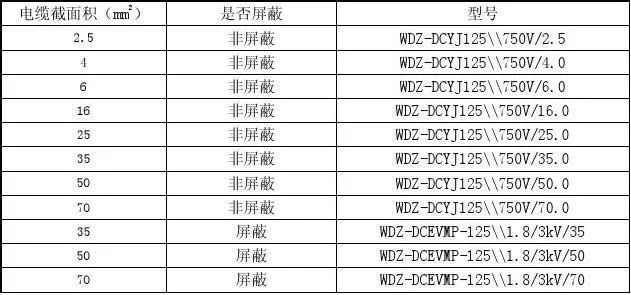
The cable model should be indicated in the wiring harness diagram, and the cable model should be selected in accordance with GB/T 12528. See Table 3 for recommended models
(8) Technical requirements for wiring harness drawings
The wiring harness diagram should contain technical requirements, specifying the notes and technical requirements for wiring harness production, etc.
(9) Drawing frame, drawing number and drawing name
The frame, drawing number and drawing name of the wire harness drawing shall comply with the company's standard Q/TEV 100.
(10) Fonts
①See Table 4 for the type of text and font height.


② When drawing drawings, the font of Chinese characters should adopt CAD default long imitation style as far as possible, and only one font is allowed to be used in the same drawing.
③ Those not specified shall be carried out according to the provisions of GB/T14691.
VI. Assembly requirements
1. Structural requirements
Hv wiring harnesses should be matched with the connected components (such as hV distribution box, motor controller, motor, auxiliary power supply, etc.) in a professional construction method under the condition of mechanical and electrical safety. An appropriate length should be reserved for the wiring harness insertion and connection part. The recommended length is 150mm, which is convenient for vehicle assembly and regular maintenance of components.
2. Cabling scheme
Wiring schemes shall assist in the removal of incorrect installations and incorrect wiring harness routing.
Large electromagnetic rings should be avoided in wiring.
The distance between high and low voltage parallel cabling must be greater than 400mm. If this requirement cannot be met, high and low voltage parallel cabling must be perpendicular to each other.
In case of collision, ensure that the wiring harness is not squeezed to prevent a short circuit caused by a broken wiring harness.
3. Requirements for wire harness fixing protectors
In view of the arrangement of high voltage wire harness, the wire harness should be protected as much as possible to minimize the relative motion between the wire harness and the car body. It is advisable to use structural parts with insulation properties, such as cable clips and cable slots. Wiring assembly should fit into smooth cable clip or cable groove. Fully protect all wire harness fixers (such as clamps and bolts) used for wiring, packaging and positioning of wire harness. Apply vaseline to prevent corrosion. The distance between the wire harness fixed protectors shall not be greater than 400mm.
4. Space requirements for wiring harness connectors
Reserve a space of at least 200mm for connecting and disconnecting connectors. Connections between connectors and parts should be properly free of mechanical stress.
5. Bend radius requirements for cable bundles
Avoid small bending radius of cable. In general, the minimum bending radius is equal to 5 times of the cable diameter. The presence of bent wires in the joint should be avoided, otherwise there may be leakage paths in the seal at the rear of the joint.
6. Waterproof requirements for wiring harness layout
Special attention should be paid to water and road abrasives that can damage wiring harnesses in the vehicle bottom and wheel well splash areas.
Connectors in the splash area should be bagged.
7. Anti-wear requirements for wiring harness layout
All hV harnesses should be protected from vibration and wear. Due to the vibration of the vehicle, the burr should be removed from the edge of the metal parts in contact with the wire harness. For the flange and rolling system, the appropriate rubber ring should be used for protection, and the rubber ring should be fixed firmly. The cable clamp used to secure the harness should be firmly attached to the equipment or frame structure and the harness.
8. Thermal protection requirements for wiring harness layout
The cable harnesses should be more than 200mm away from heat sources (such as engine exhaust pipes and large air pump copper pipes). If they cannot meet the requirements, protect all the cable harnesses to resist radiation heat sources. Use flame retardant heat insulation cotton to wrap the cable harnesses, or add heat insulation boards near the cable harnesses.
9. Isolation requirements for wire harness and moving parts
When the wire harness near the moving part (such as belt, fan, drive shaft, etc.) must be bent, fully tighten the support clip at both ends. The wiring system must be able to bend without contributing to harness wear or interference with moving parts.
VII. Specification requirements for selection of key components
1. High voltage cable: it shall comply with SAE J1654 and SAE J1673.
2. High voltage connectors: shall comply with SAE J1742
Matters needing attention:
① Protection level. With the exception of copper connectors, connectors in the combined state, wherever installed, must not be less than IP65.
(2) anti-corrosion. In order to prevent the copper joint from being duplicated, the tin plating on the surface of the copper joint shall not be damaged.
The models of copper joints are SC, T, OT, HUP and so on. Different types of copper connectors (such as SC 50-8, OT 50-8) have different widths. In view of the small wire hole, the copper joint with the same width should be selected.
④ The cross-sectional area of the crimping cable hole of the copper joint shall match that of the connected cable conductor.
The diameter of the bolt hole of the copper joint shall match the diameter of the bolt of the component.
⑤ For o-type copper joint, there are two types of FOT and OT. The differences are as follows: FOT model, the cable hole is covered with insulation jacket; OT model, the cable hole is not covered with insulation jacket.
VIII. Design and calculation
1. Cable selection
(1) Cable cross-sectional area
① Determine the load characteristics of the electrical components connected by the high voltage wiring harness. Characteristics include steady-state current intensity, voltage requirements, transient conditions and current intensity and current waveform (stationary, pulse, frequency, etc.).
② Determine the cross-sectional area of the cable according to the steady-state current intensity. At 125℃, the matching of the cross-sectional area of the common copper core cable and the current-carrying capacity is shown in Table 5.

③ If the cable layout environment exceeds the allowable working temperature of the cable, the cable with a larger cross-sectional area must be selected. When TMAX is 180℃, the conductor cross-sectional area rises one step for use, and when TMAX is 250℃, the conductor cross-sectional area rises two steps for use. For example, when the maximum current is 150A, 35mm² wire harness should be used at 125℃, 50mm² wire harness should be used at 180℃, and 70mm² wire harness should be used at 250℃.
(2) Cable structure
See Figure 1 for the structure diagram of high-voltage cables. High-voltage cables are divided into single-core cables and multi-core cables by type. The cross-section of high-voltage cables should be round. Its sheath color is orange (color GB 30). The multi-core cable is composed of multiple single-core wires which also meet the structural dimension parameters of the related conductors in the single-core cable.
The high-voltage single-core cable is mainly composed of conductor and sheath structurally. The main structural dimension parameters include single copper wire diameter, number of wires, conductor diameter, insulation diameter, inner sheath diameter and outer sheath diameter.
The high voltage cable with shielding layer is braided with bare copper or copper plated wire on the inner sheath layer; An additional band may be provided between the shield and the outer sheath; The outer sheath of the cable should be tightly packed, but not adhere to the shielding layer


(3) Cable materials
Conductor: winding tinned annealed copper.
Insulation: 120℃-200℃ class, heat resistant, halogen XLP free.
Shielding layer: tinned annealed copper wound braid.
Sheath: heat resistant 105℃-180℃, no Pb PVC (or HF-XLPO, TPE-E, PP-FR, ETFE optional).
2. Select a connector
(1) Connector structure characteristics
In addition to wire ring and copper connector, the connector shall have active locking feature. It should match the socket of the device to which it is connected.
(2) Connector performance
Connector performance requirements shall conform to SAE J1742.
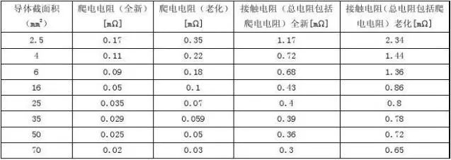
(3) Requirements for creepage resistance and contact resistance of connectors
The following resistances of the connector must not exceed the requirements of Table 6
IX. Installation and test requirements
1. Installation requirements: Refer to Point 6 of this specification
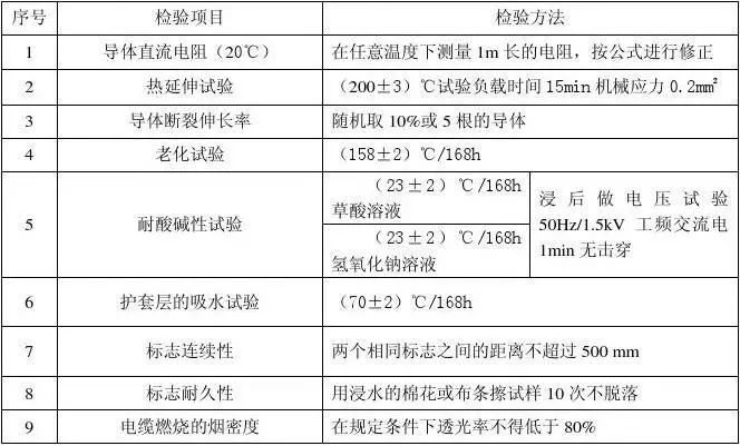
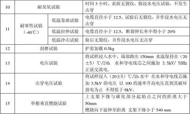
2. Test requirements: Refer to Section 7.4 of GB/T 12528-2008 for type test of cable. Specific test items are shown in Table 7.
X. Requirements for safe use
1. The operation
Do not operate high-voltage cable harnesses. Before operating high-voltage cable harnesses, professionals must use a digital multimeter to measure the dc voltage between the positive and negative terminals of the high-voltage cable harnesses and the ac voltage between the U, V, and W phases. Perform operations only when the measured value is 0V.
2. Maintenance
The high-voltage wiring harness needs to be maintained at a certain distance. According to the Maintenance Manual, the maintenance items checked every 12000km are as follows:
Check whether the cables of the high voltage wiring harness are loose between them and the connectors;
Check whether the protection such as wire hole and wire sheath is intact and whether the wire harness is worn;
Check whether the heat insulation material of the high voltage wiring harness through the high temperature area such as engine compartment falls off.
Copyright © Shenzhen Kinghelm Electronics Co., Ltd. all rights reservedYue ICP Bei No. 17113853